-
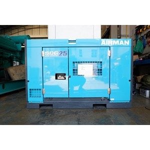
AIRMAN DENYO 20kVA-1000kVA (7)
-
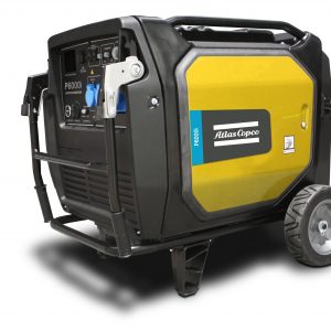
ATLAS COPCO 1.8kVA-115kVA (8)
-

CUMMINS 30kVA-2500kVA (35)
-

GENY 20kVA-1650kVA (2)
-

HONDA GENERATOR 1kVA-6.5kVA (4)
-
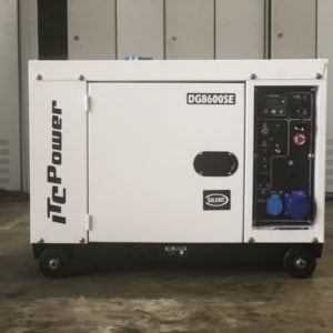
ITC POWER 5kVA-34kVA (15)
-

LOW SPEED GENERATOR (1)
-

MAN GAS GENSET 68kW-500kW (1)
-
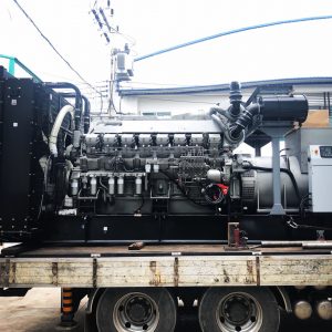
MITSUBISHI 750kVA-2500kVA (9)
-

PERKINS 10kVA-2500kVA (7)
-

SDEC GENERATOR 28kVA-1000kVA (1)
-

TURBINE (18)
-
USED GENSET 20kVA-2500kVA (1)
-

VOLVO 100kVA-625kVA (6)
Second Hand
Low speed generator (Power Plant 12.5mW)

1.Overview
1.1 General
According to the initial demand of the owner, on the basis of fully considering the local natural environment and power requirements, 5 sets of heavy oil low speeed generator units with rated power of 2250kW and relevant equipment are proposed to be selected for the power plant system described in this proposal. Three of the generators burn heavy oil and two of them burn diesel. The prime mover of the generator set is a 6WH28 diesel engine and the generator adopts famous brand high-voltage generator (11kv, 50Hz). Peripheral related auxiliary systems include fuel storage system, fuel treatment system, lubricating oil treatment system, exhaust and waste heat boiler system, cooling system, compressed air system, electrical and control system, etc.
1.2 Reference standards
- GB 755-2008 : Rotating electrical machines-Rating and performance(IEC60034-1:2004,IDT)
- GB 3906-2006 : Alternating-current metal-enclosed switchgear and controlgear for rated voltages above 3.6 kV and up to and including 40.5 kV(IEC62271-200:2003,IDT)
- GB 14048.1-2012 : Low-voltage switchgear and controlgear. Part 1: General rules
- GB 19142-2008 : Packaging for export commodity general rule
- GB/T985-2008.1 : Recommended joint preparation for gas welding,manual metal arc welding,gas-shield arc welding and beam welding
- GB/T2820-2009 : Reciprocating internal combustion engine driven alternating current generating sets. Part 1:Application,ratings and performance(ISO8528:2005,IDT)
- GB/T3216-2005 : Rotodynamic pumps. Hydraulic performance acceptance tests. Grades 1 and 2
- GB/T4025-2010 : Basic and safety principles for man-machine innterface,marking and identification. Coding principles for indicators and actuators
- GB/T10886-2002 : Three screw pumps
- GB/T13384-2008 : General specifications for packing of mechanical and electrical product
- DL/T1083-2008 : Specification of distributed control system for fossil fuel power plant
- JB/T 6434-2010 : Oil-transferring gear pumps
1.3 Operating medium
The Genset will be operated on HFO, Diesel oil is required for operating with 30mins before starting and stopping the engine. The detailed technical data of operating medium are shown as below:
Quality of heavy fuel oil
- Density(15℃) kg/m3 ≤991
- Viscosity(50℃) mm2/s ≤180
- Flash point ℃ >60
- Pour point ℃ ≤30
- Carbon residue value % (m/m) ≤22
- Sulphur content (max) % (m/m) ≤4.5
- Ash content (max) % (m/m) 0.15
- Water content (max) % (V/V) ≤0.5
- Vanadium mg/kg ≤300
- Aluminum + silicon mg/kg ≤80
Quality of diesel oil
- Density(15℃) kg/m3 ≤890
- Viscosity(40℃) mm2/s 1.5~6.0
- Sulphur content %wt ≤1.5
- Particle pollutant mg/l 10.0
- Net calorific value kJ/kg 42700
- Ash content %wt ≤0.01
- Water and deposit %wt 0.01
- Flash point of closed port ℃ ≥60
- Freezing point ℃ ≤0
Quality of lube oil
- Flash point ℃ >200
- Ash content (oxide) % <0.02
- Coke residue % <0.50
- Evaporation loss % <2
- Index of basicity KOH/g 30~40
Quality of cooling water
- Total hardness °dH ≤10
- PH value 6.5~8
- Chlorine content mg/l ≤50
Quality of intake air
- Particle size μm Max. 5
- Ash (sand, cement, CaO, Al2O3 etc) mg/m3 (standard condition) Max. 5
- Chlorine mg/m3 (standard condition) Max. 1.5
- SO2 Sulfide mg/m3 (standard condition) Max. 1.25
- H2S Sulfured hydrogen mg/m3 (standard condition) Max. 15
1.4 Operating conditions
- a) Ambient temperature: 40℃
- b) Relative humidity: 70%~100%
- c) Altitude above sea level: 20m
- d) Mildew, salt fog
1.5 Unit
In all correspondences of technical documents, schedules and drawings, metric units of all measurements shall be used.
2.Overall layout of low speed generator power station
2.1 Genset design data
2.1.1 Design environmental condition
- Engine can be operated under the following condition.
- Intake air temperature ······································· 25℃
- Atmosphere pressure ········································· 100kPa
- Cooling water temperature at engine inlet ········· 25℃
- Relative humidity ·············································· 30%
The output power of GenSet must be corrected when actual operating condition ofGenSet exceeds above requirements.
2.1.2 Basic data of low speed generator
Low speed generator body is mainly composed of engine, generator, coupling and common base, etc. The engine is connected with the generator through a coupling, and is rigidly connected with the common base in the height direction. The vibration isolator is connected between the common base and the foundation.
Generator parameter list of WPG2250S
- GenSet type WPG2250S
- Rated power(kW) 2250
- Rated speed(RPM) 750
- Rated voltage(kV) 6.6
- Rated current(A) 246
- Frequency(Hz) 50
- Power factor 0.8
- Outlet line mode Y-type, 3 phases 4 lines
- Starting mode Compressed air
- Steady-state voltage adjusting rate ≤±2.5%
- Transient voltage adjusting rate -20%~+25%
- Sudden load changing voltage steady ≤5S
- Voltage fluctuation rate ≤±1%
- Steady-state frequency adjusting rate ≤±5%
- Transient frequency adjusting rate +12%~-10%
- Sudden load changing frequency steady time ≤5S
- Frequency fluctuation rate ≤1.5%
- GenSet weight(tons) ~38
- Appearance size of generator set (mm)~7840×1931×3600
2.2 Auxiliary system for low speed generator set
2.2.1 Fuel system for low speed generator
The fuel oil system is used to provide fuel oil meeting the requirements of quality, flow, pressure, temperature, etc. for the normal operation of the generator set. Heavy oil is used as the main fuel in the long-term operation of the generator set, and it needs to be used for half an hour after the start-up and before the shutdown of the diesel engine.
The fuel oil system is designed according to relevant standards, mainly including heavy oil delivery pump station, heavy oil storage tank, heavy oil uploading module、heavy oil delivery module, heavy oil settling tank, heavy oil separation module, heavy oil daily tank, diesel storage tank, diesel uploading module、diesel delivery module, diesel daily tank, fuel oil supply unit, fuel oil pressure increasing unit, etc.
One fuel unloading pump station, one fuel pump room, one main powerhouse and one fuel tank area (outdoor layout) are set in the whole plant. The oil tank farm is arranged on the ground.
The heavy oil storage tank is equipped with 2 300m³ HFO storage tanks according to the fuel consumption of 3 units and 15 days’ operation.The diesel storage tank is equipped with a 400m³ diesel tank according to the fuel volume of two units running for 15 days.The sedimentation tanks are determined according to the 24-hour consumption of 100%MCR of the three main engines. Two sedimentation tanks of 50m³ are equipped.The daily oil tank capacity of heavy oil and diesel oil is determined according to the 12-hour consumption of 100%MCR of the main engine. The daily oil tank and diesel oil tank each have one seat of 20m³.The specific capacity of the oil tank shall be determined according
to the actual operation mode of the owner.
The equipment in the fuel pump room includes: 1 set of heavy oil delivery pump module (including 2 pumps and 1 inlet filter), 1 set of light oil delivery pump module (including 2 pumps and 1 inlet filter), 1 set of heavy oil separation module (including 2 separators), 1 set of fuel oil supply module (including 2 pumps, 1 inlet filter, 1 self-cleaning filter with slag tank and slag pump).
The main plant equipment includes: 1 sets of fuel oil booster modules (including 2 pumps and 1 inlet filter), 1 set of leakage oil tank module (including 1 set of 2m ³ oil tank, 2 pumps and 1 inlet filter).
2.2.2 Lube oil system for low speed generator
The lubricating oil system provides clean lubricating oil for the operation of the unit to meet the flow, pressure, temperature and other requirements for the operation of the unit, which is used for lubricating bearings, cylinder liners and cooling piston heads. The lubricating oil is sent to the lubricating oil cooler by the lubricating oil circulating pump with the engine from the oil pan with medium pressure and cooled by the cooling water. The temperature of lubricating oil is regulated by temperature regulating valve. The engine has an internal lubricating oil system with a wet oil pan, which can supply lubricating oil to all moving parts for lubrication and cooling. The main equipment of the lubricating oil system is as follows.
The lubricating oil system comprises a lubricating oil separator and a mobile lubricating oil pump. The three HFO generators in this project share one set of lubricating oil separator.
The lubricating oil in the finished product lubricating oil barrel is delivered to the oil pan of each machine through the lubricating oil mobile pump. The structure of the mobile lubricating oil pump is shown in Figure 3.

2.2.3 Cooling water system for low speed generator
The cooling system of the whole power station adopts horizontal air-cooled radiator, each unit is equipped with a set of cooling water circuits, which are respectively used to cool the low temperature and high temperature inside the engine. The heat of the engine cooling water is released to the atmosphere through the radiator.
Diesel engine cooling water system is divided into high temperature cooling water and low temperature cooling water two circuits: high temperature water pump will high temperature cooling water pump into the high temperature cooling water loop, the diesel engine cylinder liner, cylinder head, air cooler level for cooling;
The low temperature water pump will pump into the low temperature cooling water loop to cool the diesel engine air cooler secondary oil

2.2.4 Compressed air system for low speed generator
Compressed air system is mainly used for starting air system of engine and instrument air system of power plant.
Starting air system: the starting air system is mainly used to produce clean and dry air with a pressure of about 2.5-3.0MPa for engine starting. In this scheme, two air compressors are used and equipped with two starting air tanks. The air pressure of single air compressor is≥90m3/h, the pressure of air bottle is 30bar, and the capacity of single air compressor is 1.0m3.
Instrument air system: the instrument air system mainly provides clean and dry air with a pressure of about 0.6-0.8MPa for the use of instruments in the whole plant. In this scheme, one dryer and one instrument air tank are used, and the compressed air of the starting system is delivered to the instrument air tank after decompression and drying. The required components include 1 air bottle, pressure reducing unit, filter, valve, pipeline, etc. The pressure of air bottle is 10bar, and the capacity is 0.5m3. The schematic diagram of compressed air is shown in Figure 5.

2.2.5 Inlet air/discharging system of engine for low speed generator
The intake and exhaust system mainly refer to the relevant equipment to ensure the intake quality and exhaust noise emission of the engine when the engine intake and exhaust gas are discharged. The intake air is connected through the inlet pipe of the compressor and the intake filter of each diesel engine turbocharger.
Exhaust gas of diesel engine is discharged at the required height through waste heat utilization system, muffler and exhaust chimney. The exhaust muffler is installed at the bottom of the chimney after the waste heat boiler and bypass flue. After the exhaust gas flows through the waste heat boiler or bypass flue, it enters the exhaust muffler to eliminate noise, and then it is discharged through the chimney. The exhaust system mainly consists of exhaust muffler, exhaust pipe, chimney and its accessories.
This project is equipped with 5 air inlet filter devices.

2.2.6 Residue heat boiler system
The residue heat system uses the heat-conducting fuel boiler, utilizes the energy of engine’s exhaust gas to produce heat source to meet the thermal demands of other equipment of the power plant. This project is planning to use 3 sets of Residue heat boilers.
This system mainly consists of the residue heat boiler, boiler refill module, boiler local control box, condensing water tank, hot fuel storage tank and other equipment. The heat-conducting fuel in the residue heat boiler is heated by the engine’s exhaust gas, then the heat-conducting fuel is distributed to the heavy fuel storage tank, daily heavy fuel tank, heavy fuel separation module and fuel supply module in the fuel system. The heavy fuel is heated to different temperatures.
2.2.7 Softened water treatment system
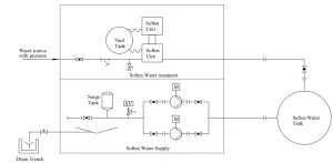
The softened water system is mainly used for filling water of circulating water in the engine, make-up water of expansion water tank and maintenance water tank, working water of lubricating oil separator, working water of oil-water separator, etc. The system is mainly used to provide water source for diesel engine, separator, etc. meeting the specification requirements.
The main equipment of softened water system includes soft water tank and softened water unit, among which, the softened water unit includes multi valve system full-automatic softener, salt tank, resin tank, water supply pump, surge tank, instrument and control box, etc. The principle of the softened water system is shown in Figure 8.
2.2.8 Residual oil / waste oil treatment system
The power plant blowdown mainly comes from the following aspects:
- Residual oil and oily waste water generated during the operation of oil separator.
- Waste diesel oil, waste lubricating oil and waste water generated during diesel engine operation.
- Waste oil and waste water generated by equipment maintenance.
- Condensate formed by diesel engine exhaust system pipe, condensate from compressed air system, cleaning water for muffler, supercharger, etc.
- Oily sewage discharged from plant and workshop cleaning.
According to the basic principle of optimizing process and simplifying equipment matching, the principle of separate collection and centralized treatment is adopted for residual oil and oily sewage. The residual oil shall be transported out regularly, and the oily sewage shall be discharged directly after reaching the standard.
According to the layout of the power station, submersible sewage pumps are set in the oil tank farm and the sewage collection well of the powerhouse. Two sets of submersible sewage pumps are selected for each sump, one for use and one for standby. four sets in total. Discharge the sewage and oil to the sump. The solid waste treatment system mainly deals with the sludge produced when the power plant uses fuel oil and lubricating oil.
2.3 Components of electrical system

According to the overall design of the electrical system of the power station.
High voltage side: 5units high-voltage synchronizing panel, single-bus configuration, 1 PT panel, 1 transformer panel and 1 unit high-voltage feeder panel the quantities is belong to customer demand,1 unit Neutral-conductor panel.
Low voltage side: 1-unit power-plant transformer,1 unit low-voltage breaker panel,1 unit distribution panel,1 unit DC screen and 1-unit 200Kw “backup” small diesel generator.
The principle of type mobile power plant electric system: 5 generator sets of 2250KW 50Hz 6.6KV; the start-up、 running and electricity generation is performed under electric control. When the voltage is stable and reaches the rating, grid-connected power generation can be carried out. Before startup of the generator sets, the required power source is provided by the black startup. As the grid is energized, automatic switching off is performed, is supplied by its own transformer, and the black startup stops.
2.4 Center control system
Each generator set is equipped with control system, with perfect protection, monitoring and control functions. The data transmission and exchange between the unit control cabinet and the Centralized monitoring screen is completed through industrial Ethernet or RS485; The control cabinet of generator sets completes the functions of data acquisition, system control, data display and data transmission. The main function of the central control board is to monitor and alarm the operation data of all units and equipment.
2.4.1 Hardware: The hardware mainly includes PLC, touch panel, industrial control machine, data exchanger, generator’s main protection, synchronization and generator’s backup protection and etc. The main hardware is famous brand products.
2.4.2 Main functions: The control system’s main functions include generator set start/stop, generator set control, data monitoring, fault alarm, historic data storage and security control.
2.4.3 Data monitoring: The control system mainly monitors the working parameters and status of the generator sets, auxiliary mechanical equipments and electrical equipments, including the working parameters and status of the engines, and the working parameters and status of the fuel system, lubrication oil system, cooling water system and compressed air system, and the power, voltage, current and frequency of the generators.
2.4.4 Security control: The security control section mainly executes start/stop of the generator set, safe stop, speed increase/decrease of engine, pressure increase/decrease of generator. The engine emergency stop button is provided on the generator set control box panel and near the generator set. In case of an emergency of the generator set, stop can be executed immediately.
2.4.5 Generator set management: This management system can perform the function control of the generator sets, realizes synchronization, parallel running, load control, voltage regulating of the generator sets.
2.4.6 Fault alarm and historic data storage and security control: The system has complete alarming function. Limit alarm is provided for analogue values, and status alarm is provided for switching volume. A special alarm menu is available and indicates all alarm status and relevant information. The alarms can be stored to provided basis for fault tracing.
2.4.7 The center control system collects the data and indicated in the IPC, and you can manage it with proprietary software.
Showing the single result
-

ขายโรงไฟฟ้า Wärtsilä Power Plant 6.3mW ใช้น้ำมันเตา


 LOGIN
LOGIN  สอบถามราคา


